Ok so recently my brother asked me to modify his nikon SB-800 flash so he could connect his wireless trigger with a 3.5mm cord rather than a PC sync (because on this sb-800 it was a flaky connection). So I decided I’d do it and turn it into a tutorial at the same time! If you can guess by the Youtube video it was a success! So coming up is a disclaimer!
**************WARNING if you proceed with this you will void any remaining warranty******************
**************DOUBLE WARNING if you proceed with this you will be exposing yourself to potentially high voltages!************
So now that the disclaimer is done here’s what you’ll need.
A Soldering iron
A 3.5mm jack (you can get it here http://www.digikey.com/product-detail/en/SJ1-3533/CP1-3533-ND/738695 )
Some wires (find some thin ones you can pick those up at a Radio shack or something or order it also from here http://www.digikey.com/product-detail/en/3050%2F1%20BK005/A3050B-100-ND/281566)
Some solder (again you can find it here http://www.digikey.com/product-search/en/soldering-desoldering-rework-products/solder/1310838?k=solder )
A Drill/Dremel tool and a good bit to drill into plastic
A small Philips screwdriver
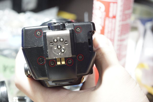
So in order to get into the SB-800 you’ll need to take apart the following screws there are 6 on the bottom shown in the photo in red. 
For the next set you’ll need to turn the flash 90 degrees to expose the next 4 as shown below also in red.
Now that the screws are out. STOP for a second and DO not pull everything apart things will fall and I may or may not have documented that. The first time I did it I pulled it apart and 2 metal plates fell down. As it turns out they were very important and were what held the top part of the flash together. Below is a photo of it (again look for the red) and where they are, look there and make a note of it’s orientation and take them off and put them in a nice place so they don’t fall out and you lose em. Also make note of the flash head direction and when you do pull the plastics apart make sure to not pull hard as there are tons of connectors and the flash head may fall so do it close to the ground.
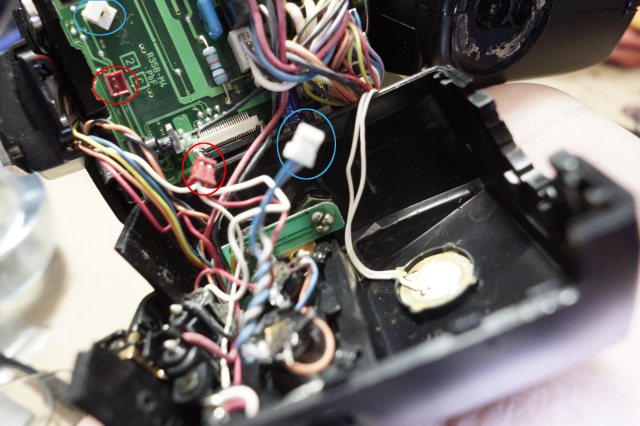
Ok so now that you are carefully taking the flash apart this is where it gets dicey. HERE IS WHERE YOU WILL BE EXPOSED TO HIGH VOLTAGES THERE ARE CAPACITORS AND THEIR TERMINALS EXPOSED WATCH OUT FOR THESE. You’ll notice that as of now it’s a bit difficult to get a good look inside, that is because there are 2 connectors you need to disconnect so that the flash comes apart easier, in the photo below they are already disconnected but highlighted in blue and red are the connectors you need to disconnect.
Ok so now we have the flash apart enough to see things. The first order of business is to drill the hole (we want to get that out of the way first because we’ll need room and if you decide to solder the new connector in there you’ll have less) Here’s where I drilled mine (look for the red), Drill lower than that unless you really don’t mind squishing everything in. IF you want drill it on the front plastic and just make sure to insulate the connectors so they don’t come in contact with any of the capacitors (glue gun the terminals or something) this will make closing it up easier but it won’t look as nice.
So the next step is to solder your 3.5mm jack to the wire. I’m not sure which jack you got but here’s a diagram I borrowed from the internet http://www.talkandroid.com/wp-content/uploads/2010/06/pinout-audio1.png?3995d3 I broke the connector out for the “right speaker” connector and just connected the ground and “left speaker” because in our project the “right speaker” connection is not used in cameras. When you have the jack wired up connect the ground to the bottom red dot and connect the “left” connection to the middle spot highlighted in red in the photo below .
Once you have that connected you can put the 3.5mm jack through the hole and screw/glue (depending on the connector you got) and then reverse the process. Just as a frame of reference mine looked like this.
So if yours looks something like that then go backwards and reassemble your flash and give it a shot! When you do that though just keep in mind you may need to hold down the flash while you screw the screws back since the jack maybe applying pressure to the cords heading into the flash head.
Enjoy! I hope that was informative!


